Design Results Reports
The Design tab is used to view Design results and to design flexure and shear rebar layouts. Click the Design Results button on the Design tab to view the Design Results screen.
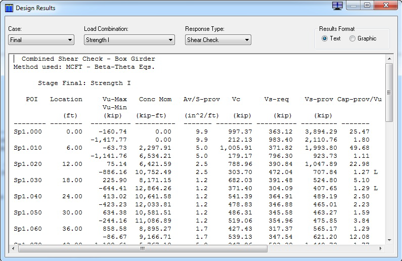
This screen can display both text and graphic analysis results. The window has three drop-down lists (five when graphical results are displayed), which allow you to select a variety of reports. The content of some of the drop-down lists is dependent on the current selection of one or more of the other drop-down lists. For example, The Load Combination drop-down lists shows the list of combinations for the selected case in the Case drop down lists.
| Setting | Description |
|---|---|
| Crack Control | This report shows the crack control/Serviceability stress and allowable stress at top and bottom of the section. This report is only applicable to reinforced sections, and will show "---" for sections with post-tensioning. |
| Required P-Jack | This report shows the required jacking force for top and bottom of each section. If no post-tensioning is present in the model, this report is not available. |
| Required f'c | This report shows the required f'c (f'ci in the Initial case) for top and bottom of each section. If no post-tensioning is present in the model, this report is not available. |
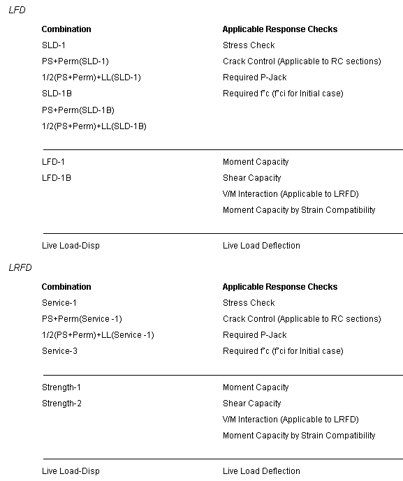
| Moment Capacity | This report shows the moment demand and capacity at each section. The moment capacity is calculated based on the selected code specifications (LFD or LRFD). The cracking moment (Mcr) is also reported for all sections, except for reinforced sections evaluated under LFD. |
| Shear Capacity | This report shows the shear demand and capacity at each section. The shear capacity is calculated based on the selected code specifications (LFD or LRFD). The shear stirrup area per unit length is also reported, and if not adequate, the required value is reported. Flags on this report indicate if shear stirrup was adequate or designed. In the case of LRFD, if the longitudinal steel is not adequate, a flag is printed to indicate this case. |
| V/M Interaction | This report is only applicable to LRFD and shows the required and available longitudinal steel needed for satisfying the shear capacity requirement. |
| Moment Capacity (SC) | This report shows the moment capacity by strain compatibility (SC) method and is especially useful for locations near the inflection point, where the tendons may not have full strength, or in cases with multiple layers of rebar. |
| Live Load-Deflection | This report shows the actual and allowable deflection for the live load shown in the combination name. |
| Other Design Reports | In addition to the reports from the Design Tab, other reports are available from the Print Report dialog box, and are only available in text form. These include the following. |
| PT Elongation | This report shows the tendon elongation. Anchor set loss forces and distances are also shown in this report. |
| Design Summary | This report shows the capacity to demand (C/D) ratios for moment, shear, tensile stress, compressive stress, and live load deflection in a concise report summarizing the controlling C/D ratios for all applicable combinations for the selected case. |
| Detailed Moment Capacity | This report shows all the applicable intermediate data that was calculated in the process of calculation of the moment capacity results. |
| Detailed Shear Capacity | This report shows all the applicable intermediate data that was calculated in the process of calculation of the shear capacity results. |